What Size Water Tank Do I Need? A Capacity Calculation Guide for Building Projects
From daily demand and storage days to fire reserve and a buildable GRP sectional layout—this is the sequence EPC and MEP teams use before the tank is specified.
Read the sizing sequence

examples
The starting formula, and why it is not enough
The water tank capacity question usually arrives early in a building project, somewhere between the first MEP coordination and the structural loading review. Get it wrong and the consequences are immediate: an undersized tank means water shortages at peak demand, pump instability, and service complaints; an oversized tank means wasted budget, unnecessary structural load, and water sitting in storage longer than it should.
For EPC contractors and project engineers, the sizing process is not complicated, but it does require more than plugging numbers into a formula. Daily demand, storage duration, fire reserve, site constraints, and panel layout all feed into the final tank specification. This guide covers each step in the sequence that leads from a rough capacity figure to a buildable GRP water tank arrangement, meaning a GRP sectional water tank layout you can install on the actual site.
Required capacity = Daily water demand × Storage duration × Safety factor
Most sizing exercises begin here. It gives a fast planning estimate before the MEP design is frozen. Commercial water tank calculators use the same logic for hotels, hospitals, offices, schools, and housing developments.
The formula is a starting point, not an answer. It does not account for fire-fighting reserve, future occupancy growth, access restrictions, structural loading limits, or maintenance clearance. A capacity figure that looks correct on a spreadsheet can still be wrong for the project if those factors are not checked before the tank layout is approved.
Estimate daily water demand
The first input is how much water the building uses in a normal operating day. At the planning stage, this is typically based on benchmark values rather than final fixture schedules.
| Building type | Typical range | Unit |
|---|---|---|
| Residential apartments | 150–200 L/day | per person |
| Hotels (guest rooms only) | 130–180 L/day | per guest |
| Hotels (with restaurant, pool, or laundry) | 250–400 L/day | per guest |
| Hospitals | 300–500 L/day | per bed |
| Schools | 50–100 L/day | per student |
| Office buildings | 50–80 L/day | per occupant |
| Shopping centers | 10–15 L/day | per m² floor area |
For industrial and process applications, manufacturing, cooling tower makeup, food processing, livestock, demand varies widely and should be confirmed with the process engineer rather than estimated from generic tables.
These benchmark figures are planning-grade numbers. They are useful for preliminary sizing but should be cross-checked against the project brief, consultant schedules, local codes, and actual supply conditions. In projects where municipal reliability is low or fixture density differs from the reference standard, the gap between benchmark and reality can be significant.
Choose the right storage duration
Storage duration is often the single biggest variable in the sizing calculation. The same building with one day of reserve may need half the tank volume of the same building designed for two days.
| Supply condition | Typical storage duration |
|---|---|
| Stable municipal supply with reliable refill | Around 1 day |
| Intermittent municipal supply | 1.5–2 days |
| Remote site or unreliable supply | 2–3 days |
| Emergency or disaster reserve | Project-specific |
| Fire protection reserve | Per fire code calculation |
The question that matters most: how dependable is the water source that refills the tank? A project with daily tanker delivery and no mains connection needs a fundamentally different storage buffer than a project connected to a pressurized utility main.
In markets where supply interruptions are common, this decision carries more weight than most generic sizing guides acknowledge. A tank sized on ideal-supply assumptions may pass a design review but fail in actual service. At the same time, increasing storage days without considering turnover creates a different problem: water sits too long, which can affect quality, especially in warm climates where biological activity accelerates.
Apply a safety factor without oversizing
A safety factor of 10–20% is standard practice for absorbing demand variation, occupancy fluctuation, and estimating uncertainty. It is not a substitute for accurate project data, and it is not a license to oversize.
A tank that holds far more water than the building actually turns over increases stagnation risk, adds structural load, raises procurement cost, and can create layout conflicts that were entirely avoidable. The question is not how large the tank can be, but what volume gives reliable operation without wasting space, budget, or water quality margin.
Separate domestic water from fire reserve
This is the step that early sizing discussions most often get wrong. Domestic storage and fire reserve are different requirements with different calculation methods, and combining them by default can create compliance problems.
Fire reserve is governed by flow rate and duration, not by daily consumption. NFPA guidance for private fire-protection water tanks sizes storage based on the required fire flow, system duration, fill rate, and water level control. A project with a sprinkler system requiring 1,500 L/min for 60 minutes needs 90 m³ of dedicated fire water, regardless of how much domestic water the building uses.
For contractors, the practical action is to confirm early whether the project needs a dedicated fire tank, a compartmentalized arrangement within a single tank, or completely separate domestic and fire storage. For dedicated fire storage, review FRP fire-fighting water tank options in parallel with the fire engineer. That decision changes the total footprint, structural loading, and piping arrangement, so it should not be deferred until after the domestic tank is already specified.
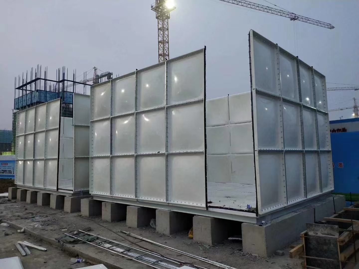
Turn capacity into a GRP sectional tank layout
Once the required volume is established, the next step is translating it into physical dimensions that work on site.
Volume = Length × Width × Height (internal/nominal per manufacturer). For GRP sectional tanks, this is not a catalogue exercise. Systems are modular: capacity is achieved by combining standard panels. Industry specifications often show common metric panel sizes of 1 m × 1 m, 1 m × 0.5 m, and 0.5 m × 0.5 m, with heights in 0.5 m or 1 m increments up to around 3–4 m in standard configurations. See how this maps to real products: SMC panel water tank ranges.
That means a target volume of 100 m³ does not correspond to one standard tank. Depending on the site, it could be a lower, wider arrangement; a taller, narrower tank; or two separate tanks if the project needs maintenance isolation, staged operation, or redundancy. The factors that determine the right layout, beyond volume, include available footprint, maximum allowable height, structural support capacity, pipe entry and exit positions, access for panel delivery, maintenance clearance, and whether the project anticipates future expansion.
Why GRP sectional tanks work for contractor-led projects
GRP sectional tanks solve a set of problems that matter more on contractor-led projects than in catalogue procurement.
Transport and site assembly
Panels ship flat and are assembled on site. When a one-piece tank cannot fit through access, or the tank is on a roof or in a basement, this is often the deciding factor.
Dimensional flexibility
Standard increments let footprint and height match the real installation location instead of accepting a fixed factory shell.
Potable suitability
GRP sectional tanks are widely described as suitable for potable water when the correct materials and project requirements are specified. Explore GRP potable water tank configurations for domestic water in commercial and mixed-use projects.
Insulation as an option. Some GRP sectional systems are available in insulated or pre-insulated configurations. Review insulated GRP water tank options when climate, exposure, and specification require thermal control, not as a default for every project.
Expansion readiness. Modular construction means some projects plan foundations and piping for future capacity additions without replacing the original tank, useful for phased developments.
Installation conditions that change the tank you need
A tank can be correctly sized by volume and still be wrong for the project if installation conditions are ignored.
Foundation
Sectional tanks require a prepared, level foundation, typically a concrete slab, support walls, or bearer beams depending on the base design. Follow manufacturer requirements and installation guidelines for level tolerances across the full foundation footprint.
Clearance
Manufacturer specifications typically require maintenance clearance on all sides. References of 450–500 mm per side appear in many sources, though exact figures depend on the tank system, flange type, and bolting method. Clearance above the inspection hatch or manway also needs to be confirmed.
Access for assembly
Panels, tie components, and internal supports must move into position during construction. If the tank is inside a plant room or on a rooftop, confirm the access path for materials and workers before the layout is finalised.
Practical rule: size the tank together with the installation envelope, not separately from it.
Worked examples
100-room hotel
100 × 1.8 × 0.80 × 180 × 1.5 × 1.15 ≈ 44,700 L. Next: fire reserve, rooftop or ground, one tank or two for maintenance.
500-bed hospital
500 × 400 × 2 × 1.2 = 480,000 L. Layout coordination matters: two tanks for redundancy, or one larger if the site allows. Confirm potable hygiene early.
200-unit residential
200 × 4 × 175 × 1 × 1.15 = 161,000 L. Limited roof load or risers may favour ground-level or split storage; feasibility, not just volume.
Industrial fire reserve
1,500 × 60 = 90,000 L. Fire reserve follows its own logic: dedicated tank, connections, and level controls as per the fire system, not the domestic formula.
If your project is past the estimation stage and you need a workable tank arrangement, ZENTVO can provide a free layout proposal based on your site conditions and capacity requirements.
Request a free tank layoutFive sizing mistakes contractors keep making
- Sizing only for average demand. Average-day figures ignore peaks, occupancy fluctuation, and supply interruption. Projects that skip a buffer step often find themselves short during commissioning.
- Combining domestic and fire water without checking codes. Fire reserve is usually governed by a separate flow-and-duration calculation. Merging it into a single domestic tank without consultant sign-off can create compliance problems that are expensive to fix after installation.
- Choosing volume before checking the installation envelope. A 100 m³ tank that cannot fit the allocated space, or that leaves no room for valve access and panel replacement, is not a finished design.
- Oversizing without considering turnover. More storage is not always better. If turnover is too slow, water sits longer than it should, a concern that intensifies in warm climates.
- Ignoring future expansion. If the project includes a later phase, a modular sectional concept is easier to expand than a fixed one-piece tank. Planning the foundation and piping for future additions at the outset costs very little compared to retrofitting later.
What to include in a tank inquiry
If you want a supplier to move from your inquiry to a usable recommendation quickly, provide more than a volume number. EPC teams evaluating delivery reliability can also review our project delivery process alongside your technical package.
Complete inquiry checklist
Typical information needed before a capacity figure becomes a confirmed sectional layout with dimensions, connection positions, and a realistic delivery schedule.
Engineering response from ZENTVO
ZENTVO’s engineering team provides project-specific structural calculations, tank layout design, and detailed CAD drawings based on these inputs, typically within 24 hours of receiving a complete brief. For capability detail and what to expect from submission to drawings, see engineering design and CAD drawing support. Sending a full package upfront is the fastest path to a layout you can build from.
Have a capacity figure and need a confirmed GRP layout?
Send your project type, daily demand, storage duration, fire reserve requirement, and available installation space to the ZENTVO engineering team. We typically return a project-specific layout with CAD drawings within 24 hours.
Assessing supplier fit for your programme? Read the project delivery process for how we move from technical review to production and site support.