By ZENTVO Engineering Team. ZENTVO designs modular water storage systems for potable water, municipal supply, industrial utility water and fire reserve projects, with engineering review before tank layout, foundation interface and installation method.
For a stainless steel bolted tank installation, approve the foundation first, keep gasket faces clean, follow the supplier’s bolt pattern, fill the tank in stages, and release the project only after a documented leak test. The critical acceptance targets are practical: foundation flatness within ±3 mm / 3 m and ±6 mm overall for modular bolted tanks, bolt torque recorded from the project torque table, no visible leakage after a 24 h hold, and a handover pack that includes drawings, nozzle schedule, test record and cleaning instructions.
Use this checklist before site assembly starts. It is written for buyers, contractors and project engineers who need a clear installation sequence for a Stainless Steel Bolted Water Tank without turning the site meeting into a vague “check everything” discussion.
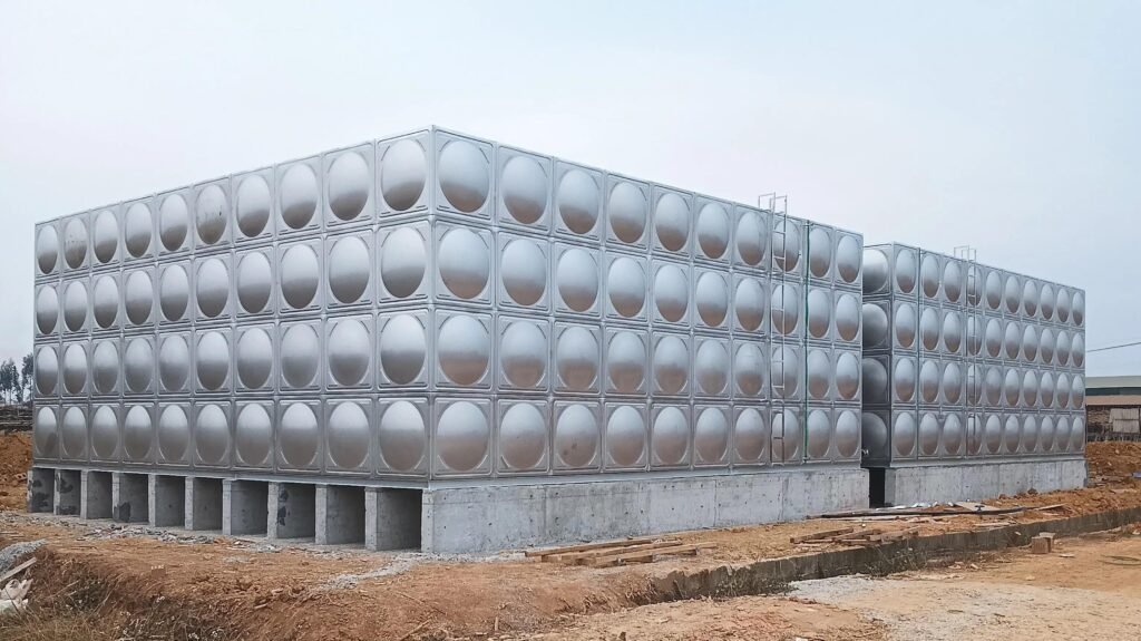
- Foundation flatness is the first hold point: use ±3 mm / 3 m and ±6 mm overall as ZENTVO’s modular tank acceptance target unless the project drawing gives a tighter value.
- Gasket sealing fails from uneven compression, because high spots overload one side of the joint while low spots leave a leak path.
- Bolt tightening needs a recorded sequence and torque table; do not use a universal torque value across different bolt diameters, gasket materials and panel thicknesses.
- Hydrostatic testing should be staged at 25%, 50%, 75% and 100% fill, with inspection after each stage and a final 24 h hold at operating level.
- Potable projects need wetted-part documentation, such as NSF/ANSI 61 or WRAS BS 6920 where the local specification requires those approval routes.
- The RFQ should include site access, foundation drawings, tank volume, nozzle schedule, water quality, indoor/outdoor location and required standards so the supplier issues the correct installation manual.
Installation Sequence At A Glance
A successful installation follows a controlled sequence: documents, foundation, materials, panel erection, accessories, testing, cleaning and handover.
Source: the flatness, staged-fill and final-hold values in this checklist are ZENTVO installation acceptance targets used with the issued project drawing and supplier installation manual.
| Hold Point | Acceptance Target | Evidence to Keep |
|---|---|---|
| Approved drawings | Tank size, panel layout, nozzles and manhole positions match the issued drawing revision | Signed drawing or marked-up approval |
| Foundation flatness | ±3 mm / 3 m, ±6 mm overall unless drawing is tighter | Level survey with date and instrument |
| Site access | Minimum access width and lifting method match panel bundle dimensions and safe handling plan | Access photo, method statement |
| Panel and gasket inspection | No shipping dents at seal lines; gasket faces clean and dry | Incoming inspection record |
| Bolt installation | Bolt grade, washer layout and torque value match the project table | Torque log by elevation or panel row |
| Nozzle and manhole fit-up | Flange rating, centerline and orientation match nozzle schedule | Nozzle sign-off sheet |
| Staged filling | 25% → 50% → 75% → 100% fill points inspected | Fill log and leak observation sheet |
| Final hold | 24 h at operating water level, no visible leakage at seams or nozzles | Hydrostatic test record |
| Cleaning and handover | Interior clean, drainable and documented before service | Handover pack and review record |
corners, drain
lower nozzles
manhole frames
Final acceptance
Pre-Installation Documents
The site should not receive panels until the installation drawing set and acceptance records are complete.
- General arrangement drawing with tank length, width, height and usable capacity in m³.
- Panel layout drawing with every wall, roof and bottom panel orientation marked.
- Foundation drawing with base size, concrete level, plinths, embedded parts and drainage route.
- Nozzle schedule with inlet, outlet, overflow, drain, vent, manhole and level-control positions.
- Material list naming stainless grade, bolt grade, washer type, gasket material and sealant if used.
- Installation manual with bolt tightening order and the project torque table.
- Potable-water documents for wetted parts when the tender names NSF/ANSI 61, NSF/ANSI/CAN 61, WRAS BS 6920 or a local drinking-water approval.
- Safety method statement for lifting, work at height and confined-space access.
The mechanism is simple: missing drawings create field decisions, and field decisions create misaligned panels, wrong nozzle orientation and uncontrolled sealing pressure. A stainless bolted tank is modular, but modular does not mean informal — every panel edge and gasket line depends on the drawing revision used by both factory and site team.
Foundation and Access Checks
Foundation acceptance comes before tank assembly because the base controls panel alignment, gasket compression and long-term leak risk.
Source: the flatness, drainage and early bearing-pressure screening values are ZENTVO installation guidance; the civil engineer’s stamped foundation design controls the final site release.
| Foundation Item | Target Value | Why It Matters |
|---|---|---|
| Local flatness | ±3 mm / 3 m | Uneven base twists the first panel row and changes gasket compression. |
| Overall level | ±6 mm overall | A tilted tank creates uneven water load and difficult nozzle alignment. |
| Drainage fall outside tank | 1:50 away | Standing water at the base causes staining, access problems and corrosion risk around fixings. |
| Soil bearing utilisation | <50% allowable | Gives the civil engineer margin for settlement, edge effects and construction tolerance. |
| Concrete condition | Clean, cured, sound | Debris under bottom rails creates point loads and seal-line distortion. |
The Water Tank Foundation Requirements for Bolted and Sectional Tanks article owns the full civil-design discussion. This installation checklist uses the values above as a site release gate for the tank crew.
Foundation Pressure Example — 80 m³ Tank
This worked example shows how to screen foundation pressure before the tank is released for installation.
Tank volume         = 80 m³
Water density load  = 9.81 kN/m³
Tank empty weight   = 25 kN
Base footprint      = 4 m × 5 m = 20 m²
Allowable bearing   = 150 kPa  (from civil engineer)
service pressure = (water load + tank dead load) / base area
water load        = 80 × 9.81          = 784.8 kN
total load        = 784.8 + 25        = 809.8 kN
service pressure  = 809.8 / 20        = 40.49 kPa
utilisation       = 40.49 / 150       = 27.0 %
Panel, Gasket and Fastener Checks
Panel and gasket inspection protects the seal line, because a small dent or dirty gasket face becomes a leak path after the tank is filled.
Source: stainless grades in this section come from the project specification, water chemistry review and ZENTVO material selection workflow.
- Stainless grade matches the order: 304 / 304L for normal potable conditions or 316 / 316L for coastal or higher-chloride service.
- Panel edges and bolt holes are free from shipping dents at sealing surfaces.
- Gaskets are stored flat, clean and out of direct sunlight before installation.
- Bolt diameter, washer layout and material match the project bill of materials.
- Gasket contact faces are cleaned before assembly; dust, metal chips and packaging fibers are removed from every joint.
- No mixed fasteners are used at wetted connections; dissimilar or unapproved hardware becomes a corrosion and traceability risk.
Under-tightened bolts leave a compression gap at the gasket. Over-tightened bolts distort the panel edge or extrude the gasket. Both conditions lead to the same failure mode: water pressure finds the lowest-resistance path along the seam. That is why installation records should state the torque value from the supplier table, the tightening pattern and the inspection date — not only the sentence “bolts tightened.”
Erection Sequence and Bolt Tightening
The tank should be erected from a square, level starting row, then tightened in a controlled cross-pattern so the gasket sees even compression.
- 1 Mark the base line and centerline on the accepted foundation.
- 2 Install the bottom rail, base frame or first bottom panel row according to the issued drawing.
- 3 Set corner panels first and brace them before installing long wall runs.
- 4 Fit wall panels row by row, keeping bolt holes aligned without forcing panels into position.
- 5 Install gaskets continuously at panel joints, with no folds, twists or debris.
- 6 Insert bolts finger-tight across the joint before final torque.
- 7 Tighten in a cross-pattern or supplier-specified sequence from the center of the joint toward the ends.
- 8 Record final torque after the first pass and after the second pass.
- 9 Re-inspect high-risk joints after staged filling, especially bottom corners, nozzle reinforcement plates and manhole frames.
Nozzles, Manholes and Accessories
Nozzle alignment should be approved before leak testing because pipe stress at a flange can pull a sealed tank joint out of tolerance.
| Item | Installation Target | Record Required |
|---|---|---|
| Inlet | Position and flange rating match nozzle schedule | Photo plus nozzle tag |
| Outlet | Centerline height supports usable volume requirement | Drawing mark-up |
| Overflow | Diameter and discharge route sized by project design | Drainage approval |
| Drain | Lowest practical point, accessible valve, safe discharge route | Drain test record |
| Vent | Sized to avoid vacuum or pressure during fill and drawdown | Vent screen inspection |
| Manhole | Accessible for cleaning, gasket seated, cover bolted evenly | Access sign-off |
| Level sensor | Installed away from inlet turbulence where drawing requires | Instrument sign-off |
| Ladder / platform | Work-at-height protection follows site safety plan and applicable law | Safety inspection record |
Pipework should be supported independently of the tank shell. Unsupported pipe loads lead to flange rotation, which concentrates stress at the nozzle plate and gasket. For potable tanks, all wetted seals, coatings, gaskets and sealants should follow the specified drinking-water approval route, such as NSF/ANSI 61 in North American projects or WRAS BS 6920 in UK-linked specifications.
Leak Test and Commissioning
Leak testing should fill the tank in stages, because staged loading finds installation errors before the full hydrostatic load is applied.
- 1 Clean the tank interior and remove loose debris before water enters.
- 2 Fill to 25% of operating water level and inspect bottom seams, corners, drain and first-row bolts.
- 3 Fill to 50% and inspect wall joints and lower nozzles.
- 4 Fill to 75% and inspect vertical seams, manhole frames and nozzle reinforcement plates.
- 5 Fill to 100% operating water level and hold for 24 h.
- 6 Record water level, start time, finish time, weather or room condition, visible leakage observations and corrective actions.
- 7 Drain or clean the tank according to the potable-water commissioning method before service.
Acceptance should be practical and visible: no active dripping, no wet seam line that grows during the hold period, and no nozzle seepage after pipe supports are connected. If a leak appears, lower the water level below the leaking joint, clean the area, correct the gasket or bolt condition, and repeat the affected fill stage. Do not smear sealant over a pressurized seam and call it complete; that hides the cause instead of fixing the compression path.
Standards and Approval References
Installation documents should separate structural tank standards, drinking-water contact approvals, safety rules and quality-system evidence.
| Reference | Where It Applies During SS Bolted Tank Installation |
|---|---|
| AWWA D103 | Bolted steel water tank design, fabrication and erection — when specified for the project. |
| AWWA C652 | Disinfection procedure for potable-water storage facilities in North American specifications. |
| NSF/ANSI 61 | Health-effects evaluation for materials and products in contact with drinking water. |
| WRAS BS 6920 | UK water-contact testing route for non-metallic and wetted components. |
| OSHA 1926-M | Fall-protection for U.S. construction work at height; local law controls outside the U.S. |
| ISO 9001 | Quality management system reference for supplier document control and corrective actions. |
RFQ Input List and Specification Checklist
The best installation support starts before purchase, because the supplier needs the site constraints before it prepares drawings and instructions.
- Required tank volume in m³ or litres.
- Tank footprint limit, height limit and indoor/outdoor location.
- Foundation drawing, available base size and access route.
- Stored water type: potable, fire reserve, municipal, process, RO permeate, rainwater or utility water.
- Stainless grade preference: 304 / 304L / 316 / 316L, with chloride level in mg/L for grade review.
- Nozzle schedule with inlet, outlet, overflow, drain, vent, manhole and instrumentation ports.
- Required standards: AWWA D103, AWWA C652, NSF/ANSI 61, WRAS BS 6920, ISO 9001 or local approval route.
- Site installation responsibility: buyer contractor, supplier supervisor or full installation team.
- Required handover records: torque log, fill test, cleaning record, photos, material certificates and operation guide.
ZENTVO’s Installation Guidelines page is the right next internal reference when the buyer needs drawings, installation coordination and quotation support. For material-specific inquiries, compare the 304 Stainless Steel Water Tank and 316 Stainless Steel Water Tank pages before sending the final grade.
Frequently Asked Questions
What is the most important check before stainless steel bolted tank installation?
The most important check is foundation acceptance before panel assembly starts. Use ±3 mm / 3 m and ±6 mm overall as the working target unless the issued drawing is stricter. A flat base keeps the first panel row square, which keeps gasket compression even during filling.
How long should a stainless steel bolted tank leak test run?
A practical leak test fills the tank in 25%, 50%, 75% and 100% stages, then holds the operating level for 24 h. Inspect seams and nozzles after each stage. The pass condition is no visible dripping, no growing wet seam line and no nozzle seepage under the final hold.
Which documents should be in the installation handover pack?
The handover pack should include approved drawings, material list, nozzle schedule, bolt torque log, staged fill record, 24 h leak-test record, cleaning or disinfection record, inspection photos and operation guidance. Potable-water projects should also include wetted-part documentation for NSF/ANSI 61, WRAS BS 6920 or the named local approval route.
Why do gasket faces need cleaning before assembly?
Gasket faces need cleaning because dust, metal chips and packaging fibers create a small channel through the compressed joint. Water pressure then follows that channel along the seam. A clean, dry gasket face and even bolt compression reduce leak risk more reliably than adding sealant after filling.
Is one bolt torque value enough for every tank joint?
One bolt torque value is not enough when the tank uses different bolt diameters, gasket materials,
washer layouts or panel thicknesses. The installation record should use the supplier’s project
torque table and list each fastener size, such as M12 or M16, with the
corresponding joint type and inspection pass.
- American Water Works Association (AWWA) — publishes standards used in water-storage design, construction and disinfection specifications, including AWWA D103 and AWWA C652.
- NSF/ANSI/CAN 61 — covers health-effects requirements for drinking-water system components.
- WRAS BS 6920 testing requirements — describe UK water-contact testing for non-metallic materials and products used with wholesome water.
- OSHA 1926 Subpart M — provides fall-protection requirements for U.S. construction work.
- ISO 9001 — defines a quality management system framework used for document control, inspection and corrective-action processes.
Ready to Specify a ZENTVO
Stainless Steel Bolted Tank?
Send your project requirements and get a project-specific engineering proposal, drawing package support and quotation from the ZENTVO team.