This is the engineering reference for the foundation under modular water storage tanks — bolted steel, pressed steel sectional, GRP/FRP sectional, glass-fused-to-steel, and fire water tanks. Written for civil and structural engineers, EPC project managers, and contractors who must confirm the foundation before tank production starts.
If the foundation fails, the tank fails — regardless of how well the panels are manufactured. Most tank field problems trace to foundation flatness, settlement, or anchorage — not panel defects.
8 Items to Confirm Before Tank Production
The single most common project delay: civil works completed to general “flat slab” tolerance (±10–15 mm), panel installation begins, fitter discovers ±15 mm against the ±3 mm / 3 m requirement. Remediation: slab grinding or grout topping — 7 to 14 day schedule impact. Specify the tank flatness tolerance to the civil contractor at bid stage, not at installation.
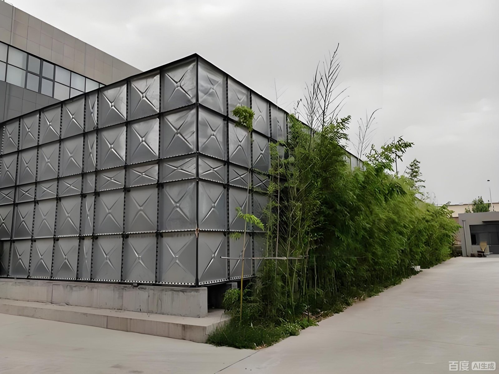
Load Path — Stored Water to Soil
σ_bearing = (W_water + W_tank + W_roof + W_app + W_live) / A_base

W_water  = V × 1000 kg/m³ × 9.81 m/s²     (dominates for H ≥ 2 m)
σ_hydro  = 9.81 kN/m³ × H                (hydrostatic at tank floor)
| Load source | Typical magnitude | Reference |
|---|---|---|
| Stored water | 9.81 kN/m³ × H — dominates for H ≥ 2 m | EN 1991-4 |
| Tank self-weight (bolted steel) | 0.5–1.5 kN/m² of base | AWWA D103 |
| Tank self-weight (GRP sectional) | 0.3–0.6 kN/m² of base | Project |
| Roof + appurtenances | 0.5–1.0 kN/m² | Project |
| Live (maintenance) | 1.5 kN/m² roof · 0.75 kN/m² walkway | EN 1991-1-1 |
| Wind (empty tank) | Per ASCE 7 Ch26 / EN 1991-1-4 | Governs uplift |
| Seismic | Per ASCE 7 Ch15 / EN 1998-4 | Impulsive + convective |
Worked (200 m³, 8×5×5 m, A_base = 40 m²): W_water = 200 × 9.81 = 1,962 kN · tank self-weight 32 kN · total ≈ 2,000 kN → σ_bearing ≈ 50 kPa average. On medium-dense sand (SPT N ≥ 25, q_allow ≈ 200 kPa) → utilisation 25 % ✓
Foundation Type Decision Matrix
Default choice for rectangular bolted and pressed steel sectional tanks on competent soil.
Standard for circular bolted tanks. Ring supports shell; granular pad supports floor.
Distributes load across the full base area when soil is soft or non-uniform.
Transfers load to deeper competent layer when surface soils are inadequate.
Structural engineer designs frame; tank tolerance (±3 mm / 3 m) shifts to frame levelness.
Plinths under panel joints on existing hard surface. Layout must match supplier base drawing.
Foundation Flatness Tolerances by Tank Type
| Tank type | Local flatness | Overall levelness | Reference |
|---|---|---|---|
| Bolted steel (AWWA D103) | ±3 mm / 3 m | ±6 mm overall | AWWA D103-09 §15 |
| Glass-fused-to-steel | ±3 mm / 3 m | ±6 mm overall | ISO 28765 / supplier |
| Pressed steel sectional (BS 1564) | ±3 mm / 3 m | ±6 mm overall | BS 1564 / supplier |
| GRP / FRP sectional | ±5 mm / 3 m | ±10 mm overall | Supplier specification |
| Welded steel (small) | ±6 mm overall | Per shell circumference | API 650 App. B |
| Welded steel (D > 30 m) | ±13 mm overall | Per API 650 §B.4 | API 650 App. B.4 |
| Round bolted — ring beam seating | ±3 mm circumferential | Concentric ±15 mm | AWWA D103-09 §15 |
Verification method: optical level or laser level grid at ≤ 1 m spacing across full slab. Tank supplier site supervisor signs off before panel arrival. Non-conforming areas: grind high spots or apply levelling grout.
Differential Settlement Limits
| Tank type | Settlement limit | Total limit | Reference |
|---|---|---|---|
| Steel bolted modular | L / 500 | 50 mm preferred | AWWA D103 / EN 1997 SLS |
| Glass-fused-to-steel | L / 500 | 50 mm | Supplier |
| Pressed steel sectional | L / 500 | 50 mm | Supplier |
| GRP / FRP sectional | L / 300 | 75 mm | Supplier |
| Welded steel | L / 500 (shell) | 50 mm | API 650 App. B |
| Concrete tanks | L / 750–1000 | 25 mm | ACI 350 / EN 1992-3 |
Foundation Requirements by Tank Type
Bolted Steel Water Tank
- Ring beam (round) or full slab (rectangular) per §15
- Flatness: ±3 mm / 3 m, ±6 mm overall
- Concrete grade: C30/37 for shell-bearing ring beam
- Anchor bolts cast-in per shell hold-down detail
- Granular pad inside ring beam: 200–300 mm compacted + 50 mm sand topping
- Ring beam width: 300–500 mm (matched to shell chair plate)
Pressed Steel Sectional Tank
- Continuous concrete plinths under panel joints, or full slab
- Bearing area: 1 m² per panel grid (≈ 1 t per metre water depth per m²)
- Flatness: ±3 mm / 3 m
- Drainage tray for indoor / basement plant rooms
- Plinth grid must match supplier base layout drawing exactly
- Lean-mix blinding (50 mm C10) under plinths
Glass-Fused-to-Steel Tank
- Same ring beam design as AWWA D103 bolted steel
- Flatness: ±3 mm / 3 m — panel chipping risk if forced onto uneven base
- Anchor design per AWWA D103-09 §15
- Foam gasket under base rail — ensure flat bearing for gasket compression
- Concrete grade C30/37 minimum for ring beam
GRP / FRP Sectional Tank
- Continuous support under every panel joint — typically steel I-beams or RC beams on 1 m grid
- Flatness: ±5 mm / 3 m (panels more tolerant, but joints concentrate load)
- Beam grid must match supplier base layout — not interchangeable
- Differential settlement limit: L/300 (more lenient than steel)
- Anti-vibration pads under beam-to-plinth contact where pumps are nearby
Fire Water Storage Tank
- Foundation must support full standby load indefinitely — fire reserve water sits without turnover
- Independent pipe support for fire pump suction within 1 m of nozzle — avoid nozzle stress on tank shell
- Drainage and corrosion protection where stagnant seepage may accumulate
- Seismic anchorage required per NFPA 22 §14 in applicable zones (Zone 2A or higher)
- Pump suction outlet position must be confirmed before foundation pour (submergence H_sub calculation per NFPA 20 §4.15)
Anchor Design — Seismic and Wind Uplift

Anchors are required when any of the following triggers apply:
| Trigger | Reference |
|---|---|
| Seismic Zone 2A or higher per ASCE 7 | NFPA 22 §14 |
| Tall slender tanks (H/D > 2) in wind zones | API 650 §5.12 |
| Empty tank wind uplift | ASCE 7 Ch26-30 / EN 1991-1-4 |
| Tanks in flood zones (buoyancy) | IBC Ch16 |
| AHJ or insurer requirement | Project-specific |
Uplift per anchor (simplified):
Uplift_per_anchor = (M_overturning − M_resisting) / (n × r)

M_overturning = C_s × W_eff × H_cog
M_resisting  = W_empty × R_tank / 2
n = number of anchors · r = anchor radius from tank centre

Bolt material: HDG grade 8.8 standard · A4 (316) stainless for coastal / aggressive
Embedment depth: ≥ 10 × bolt diameter
| Anchor type | Application | Reference |
|---|---|---|
| Cast-in-place J-bolt (M16–M30) | New construction — preferred | ACI 318 Ch17 / EN 1992-4 |
| Cast-in-place anchor plate | Heavy seismic loads | ACI 318 Ch17 |
| Post-installed mechanical anchor | Retrofit on existing slab | ETA / ICC-ES report |
| Chemical / epoxy anchor | Retrofit, vibration-prone | ETA / ICC-ES report |
Worked Example — 200 m³ Bolted Steel Tank Foundation
50 kPa average±3 mm / 3 m, ±6 mm overall8 × M20 HDG J-bolts cast-in at corners and mid-sides · Embedment 250 mm (≥ 10 × 20 mm)
Failure Modes to Prevent
Common Mistakes — and Their Project Cost
| Mistake | Typical project cost |
|---|---|
| “Flat slab” tolerance (±10–15 mm) instead of ±3 mm / 3 m | 7–14 day delay, slab grinding or grout topping |
| No soil report — assumed bearing capacity | Foundation re-design at tender; sometimes complete redo |
| Anchor positions not surveyed before tank delivery | Site drilling, coating repair, delayed handover |
| Tank ordered before foundation drawing issued | Incompatible tank and foundation dimensions |
| Pipework hung from tank nozzles | Year 1–3 leak, nozzle failure, full pipework re-support |
| Drainage afterthought | Persistent water at tank base, accelerated coating failure |
| Ring beam too narrow for shell bearing plate | Shell unsupported — ring beam redo |
| Wrong concrete grade (generic flatwork, not ACI 350) | Cracking, rebar corrosion, premature decay |
Standards Reference Quick Card
ZENTVO Engineering Assist — Foundation
Engineer-to-engineer contact. Send the foundation inputs; ZENTVO returns the drawings and calculations within 24 hours.
Foundation reaction drawing
Filled tank reactions, anchor positions and base detail — issued standard with GA drawing. Civil engineer designs the foundation against site soil and local code.
Request GA + foundation drawing →Flatness dispute — remediation plan
Already in construction with a tolerance dispute? Send the as-built level survey — ZENTVO returns a remediation plan (grind, grout, or accept) within 24 hours.
Email survey to info@zentvo.com →Anchor schedule
Bolt grade, diameter, embedment, layout and uplift calculation — included in the submittal package for seismic or wind-exposed projects.
Request anchor schedule →BIM Revit family
Revit .rfa / IFC including foundation interface plane — for BIM coordination at tender stage.
Request BIM files at /resources/ →Frequently Asked Questions
What is the foundation flatness tolerance for a bolted steel water tank?
How thick should a concrete slab be for a water tank?
What allowable bearing pressure does a water tank slab need?
When do I need anchor bolts?
What is differential settlement and why does it matter?
Can I install a tank on an existing slab?
What changes for a rooftop tank?
What is the most common foundation mistake on tank projects?
Who issues the foundation drawing — tank supplier or civil engineer?
Ready for foundation engineering review?
Send tank capacity, dimensions, soil report and local code. ZENTVO returns the foundation reaction drawing, anchor schedule and levelness verification procedure within 24 hours.
Validate a slab design
Send tank GA + soil report. Foundation reaction drawing and acceptance template returned within 24 h. info@zentvo.com
Tolerance dispute on site
Send the as-built level survey — ZENTVO returns grind / grout / accept remediation plan within 24 hours.
Project-stage RFQ
Send the 10-item foundation information list. GA + foundation drawing returned within 24 h. +86 153-1889-6990